The design of DAF (Dissolved Air Flotation) equipment involves several critical considerations to ensure efficient separation of suspended solids or oil droplets from wastewater.
1. Flow Rate and Hydraulic Retention Time (HRT)
- Flow Rate: The equipment must be sized to handle the target wastewater flow (e.g., m³/h), ensuring the flotation tank’s cross-sectional area allows for optimal upward liquid velocity (typically 1–3 mm/s). Mismatched flow rates can cause short-circuiting or insufficient particle attachment.
- HRT: The retention time in the flotation tank (usually 10–30 minutes) must be adequate for air bubbles to attach to contaminants and rise to the surface. Shorter HRT reduces separation efficiency, while excessive HRT increases equipment size and cost.
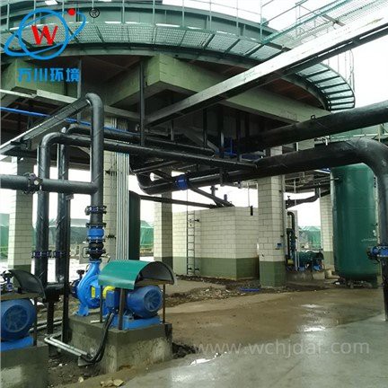
2. Air Dissolution System Design
- Dissolved Air Pressure: The air dissolution tank (or saturator) should operate at 3–5 bar to ensure sufficient air solubility in water. Higher pressure enhances bubble density but requires robust tank construction; lower pressure may produce too few bubbles.
- Recycling Ratio: Typically, 10–30% of the treated water is recycled through the saturator to generate dissolved air. A higher ratio increases bubble supply but may reduce energy efficiency. Proper calculation based on pollutant concentration is essential.
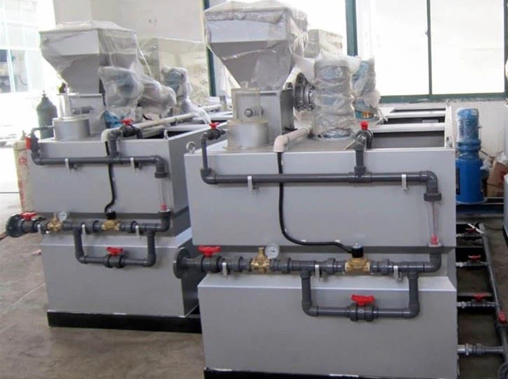
3. Flocculation and Contact Zone Design
- Flocculation Chamber: Prior to the flotation tank, a well-designed flocculation zone ensures contaminants form stable flocs. Mixing intensity (G value: 20–80 s⁻¹) and detention time (5–15 minutes) must balance particle aggregation without shearing flocs. Chemical dosing (e.g., coagulants like PAC or PAM) is critical for charge neutralization.
- Contact Zone: The interface between the flocculation chamber and flotation tank should promote rapid bubble-floc attachment. A gentle upward flow (avoiding turbulence) and sufficient contact time (1–3 minutes) maximize particle-bubble adhesion.
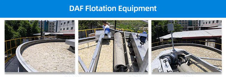
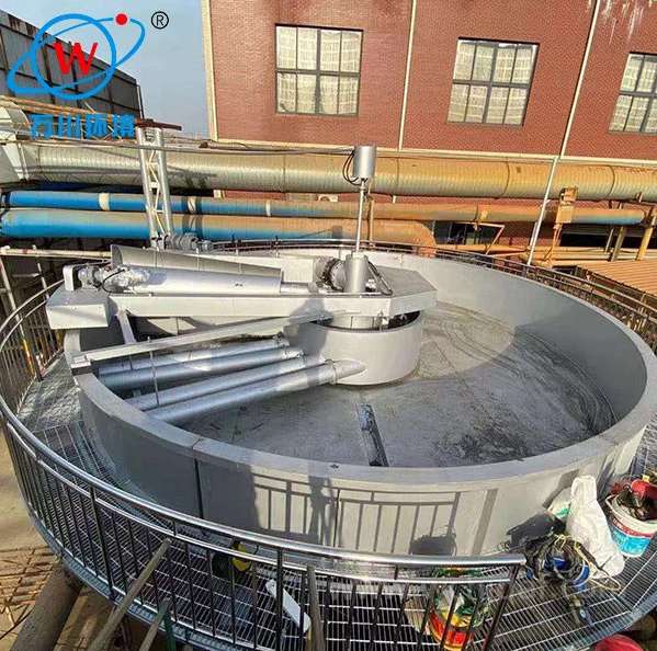
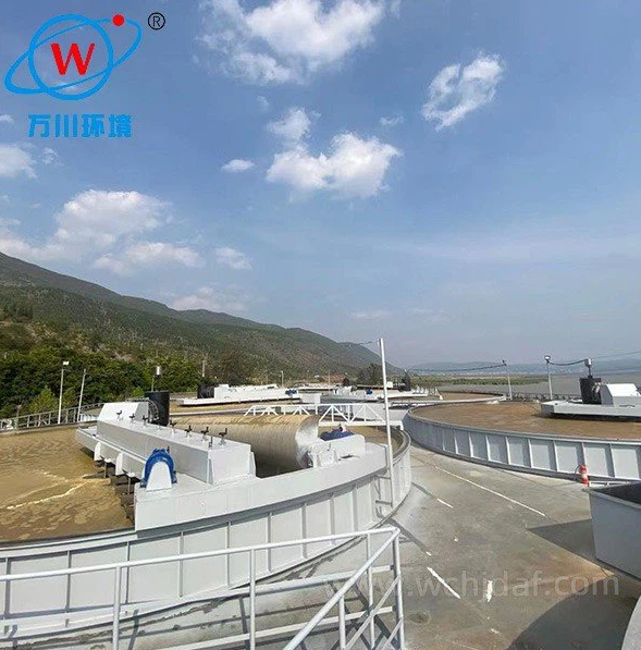
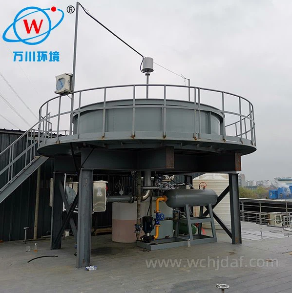
4. Flotation Tank Geometry
- Tank Shape: Rectangular tanks are common for easy sludge scraping, while circular tanks may offer uniform flow distribution. The tank depth should be 2–4 meters to balance settling of heavy solids and bubble rise efficiency.
- Inlet and Outlet Design: Inlets should introduce wastewater tangentially or vertically to minimize turbulence, while outlets (weirs or effluent channels) must prevent disturbing the floating sludge layer. Proper baffle placement directs flow and reduces short-circuiting.
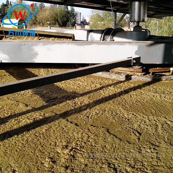
5. Sludge Removal System
- Skimming Mechanism: Mechanical scrapers (chain-driven or bridge-mounted) should operate at low speeds (0.5–2 m/min) to avoid breaking the sludge blanket. The slope of the tank floor (1–2%) aids sludge drainage to the collection hopper.
- Sludge Holding Capacity: The hopper volume must accommodate sludge retention for periodic discharge, preventing re-entrainment of solids into the treated water.
6. Energy Efficiency and Maintenance
- Air Compressor and Pump Sizing: Over-sized compressors or pumps increase energy costs. Select equipment based on dissolved air demand (typically 0.5–1.5 m³ air/m³ wastewater) and hydraulic requirements.
- Accessibility: Design should facilitate easy cleaning of nozzles, filters, and tanks to prevent clogging. Anti-corrosion materials (e.g., stainless steel for wetted parts) enhance durability in harsh wastewater environments.
7. Process Control and Monitoring
- Key Parameters: Install sensors to monitor dissolved air pressure, flow rates, pH, and turbidity of influent/effluent. Automated control systems (e.g., adjusting chemical dosing or recycling ratio) optimize performance in real time.
-
Pilot Testing: For complex wastewaters, pilot-scale DAF testing helps determine optimal design parameters (e.g., flocculant type, air-to-solid ratio) before full-scale implementation.